This article guides the configuration of IPsec Site-to-Site VPN between two Sophos Firewall XGS devices using firmware v22, in order to establish a secure connection between two network systems located at two different sites.
Objectives of the lab:
- Successfully establish an IPsec tunnel between the two firewalls.
- Allow the two LAN networks at the two sites to access and exchange data with each other.
- Ensure that all traffic transmitted through the Internet is securely encrypted.
- Check and verify the operating status of the VPN Tunnel.
- Clearly understand the operation mechanism of Phase 1 (IKE SA) and Phase 2 (IPsec SA) in the VPN establishment process.
Deployment environment:
- 02 Sophos Firewall XGS (Virtual Appliance).
- Installed on the Proxmox VE virtualization platform.
- Both ends use static WAN IP addresses, provided by a real firewall/router to simulate a real environment.
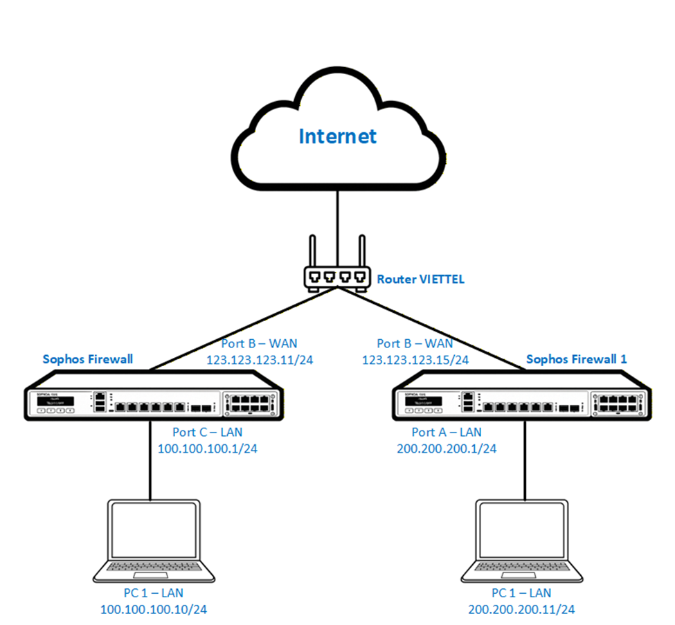
The enterprise has two sites using two Sophos Firewall XGS devices connecting to the Internet through a Viettel router with WAN IP addresses 123.123.123.11 and 123.123.123.15 respectively.
Each site has its own LAN network which is 100.100.100.0/24 and 200.200.200.0/24.
Currently these two networks cannot access each other through the Internet.
The requirement is to allow the two LAN networks to communicate securely and stably.
The solution is to deploy an IPsec Site-to-Site VPN to encrypt and connect the two systems through the Internet.
- Prepare configuration information
- Create Network Object (Host/Subnet)
- Configure IPsec Site-to-Site VPN
- Create Firewall Rule to allow LAN ↔ VPN traffic
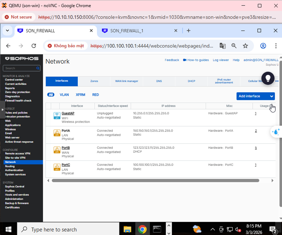
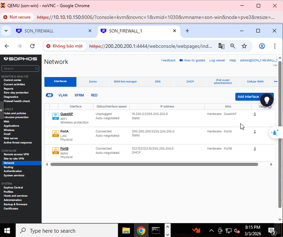
Step 1: Check the interface configuration. On Sophos Firewall 1, the WAN port IP is 123.123.123.11, and LAN is 100.100.100.1/24.
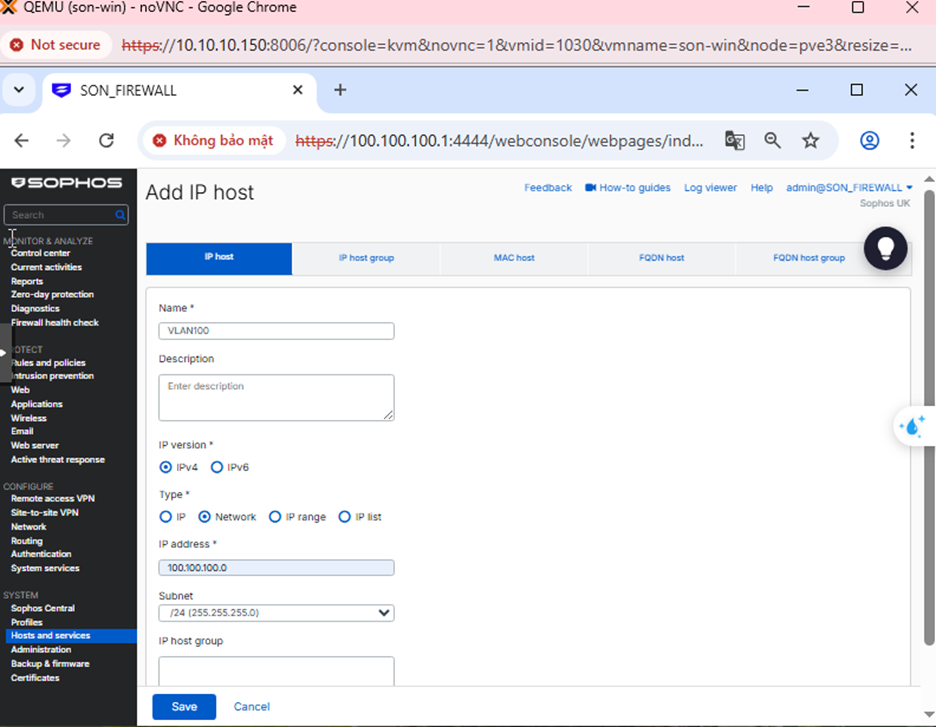
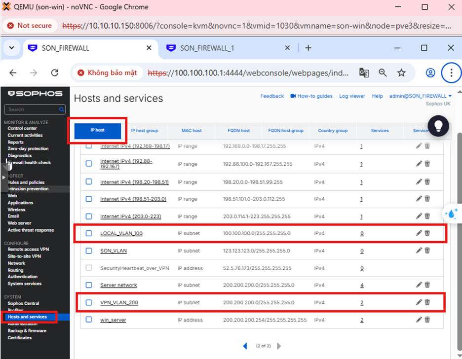
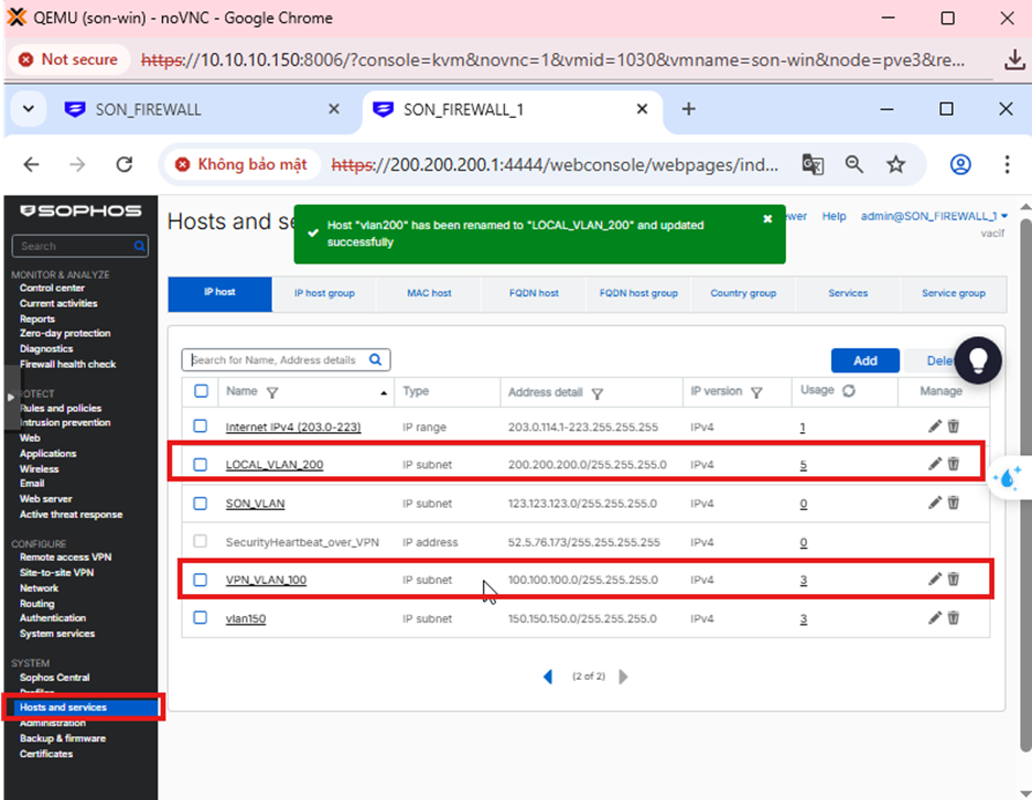
Step 2: Add Local and Remote LAN Network
Go to Hosts and services → IP Host → Add to add the local and remote LAN network as shown in the image below.
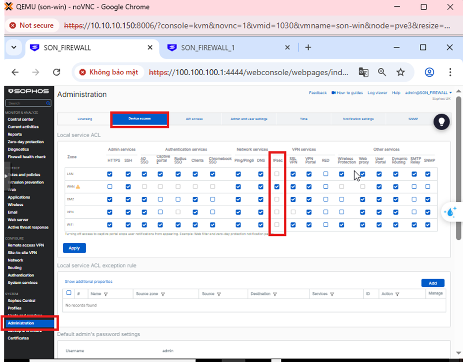
Step 3: Go to Administrator → Device Access → WAN: check IPsec
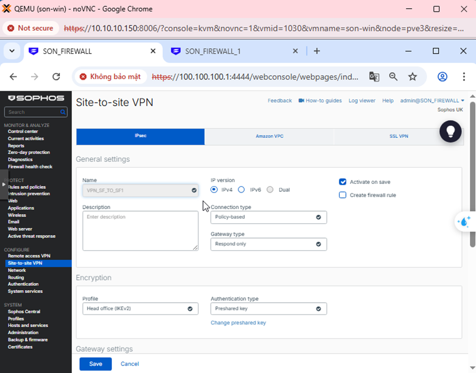
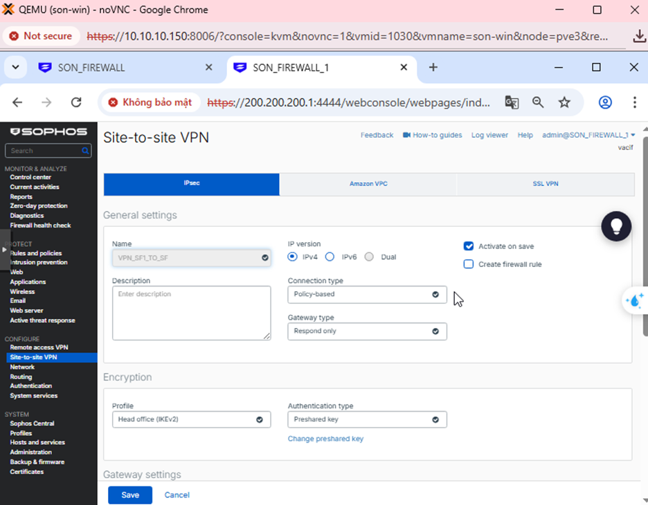
Step 4: Create IPsec Connection
Go to Site to site → IPsec → Add
- IP Version: IPv4 → The tunnel uses IPv4 addresses to establish IKE and transmit ESP data.
- Connection Type: Policy-based → Only the subnets declared in Local subnet and Remote subnet are allowed to pass through the tunnel.
- Gateway Type: Respond only → This firewall does not initiate the connection, it only responds when the other side initiates it.
- Profile: IKEv2 → A newer VPN standard, more stable and secure than IKEv1.
- Authentication: Preshared Key (PSK) → Both firewalls use the same shared secret password.
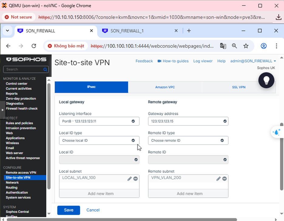
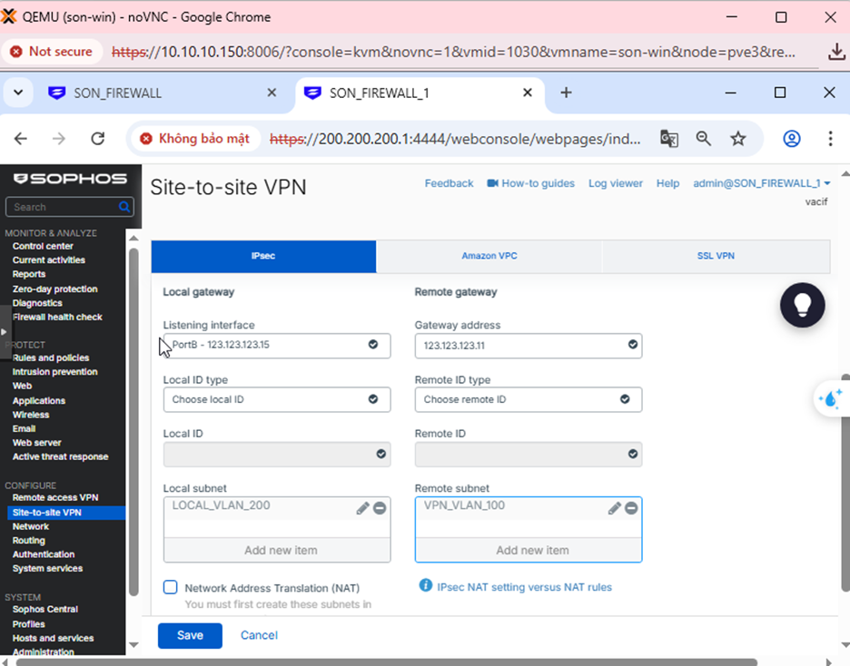
- Listening interface: 123.123.123.11 → This is the WAN IP of this firewall, the firewall will wait for VPN connections at this IP.
- Gateway address: 123.123.123.15 → This is the WAN IP of the other firewall, the VPN will connect to this IP.
- Local Subnet: LOCAL_VLAN_100 → The internal network on this side that is allowed to pass through the VPN.
- Remote Subnet: VPN_VLAN_200 → The internal network on the other side.
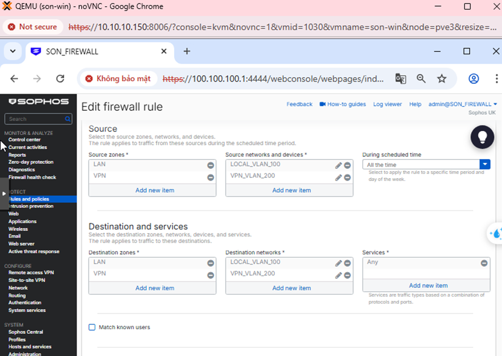
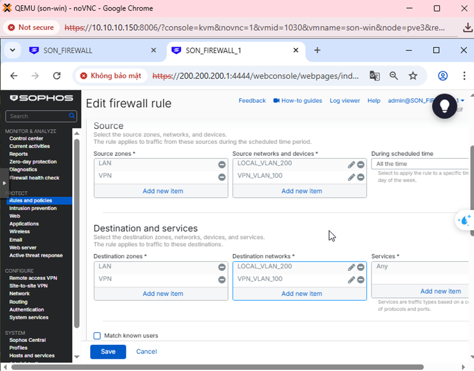
Step 5: Create Firewall Rule
- Rule name: VPN_SF_TO_SF1
- Action: Accept → Allow traffic to pass
- Log firewall traffic: Check → Log traffic for verification when necessary
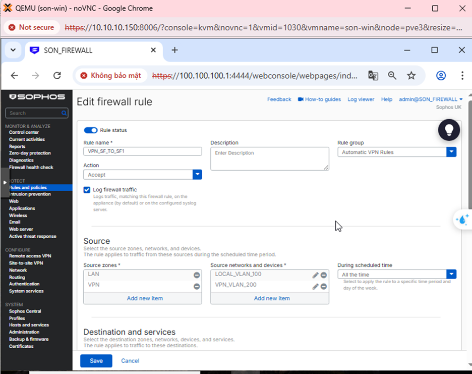
- Source zones: LAN, VPN → Meaning traffic can originate from the internal network or from the VPN side.
- Source networks: LOCAL_VLAN_100, VPN_VLAN_200 → Only these networks are allowed to use this rule.
- Destination zones: LAN, VPN → Allow two-way access between LAN and VPN.
- Destination networks: LOCAL_VLAN_100, VPN_VLAN_200
- Services: Any → Allow all services (ping, RDP, SMB, HTTP…)
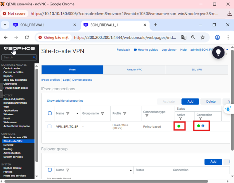
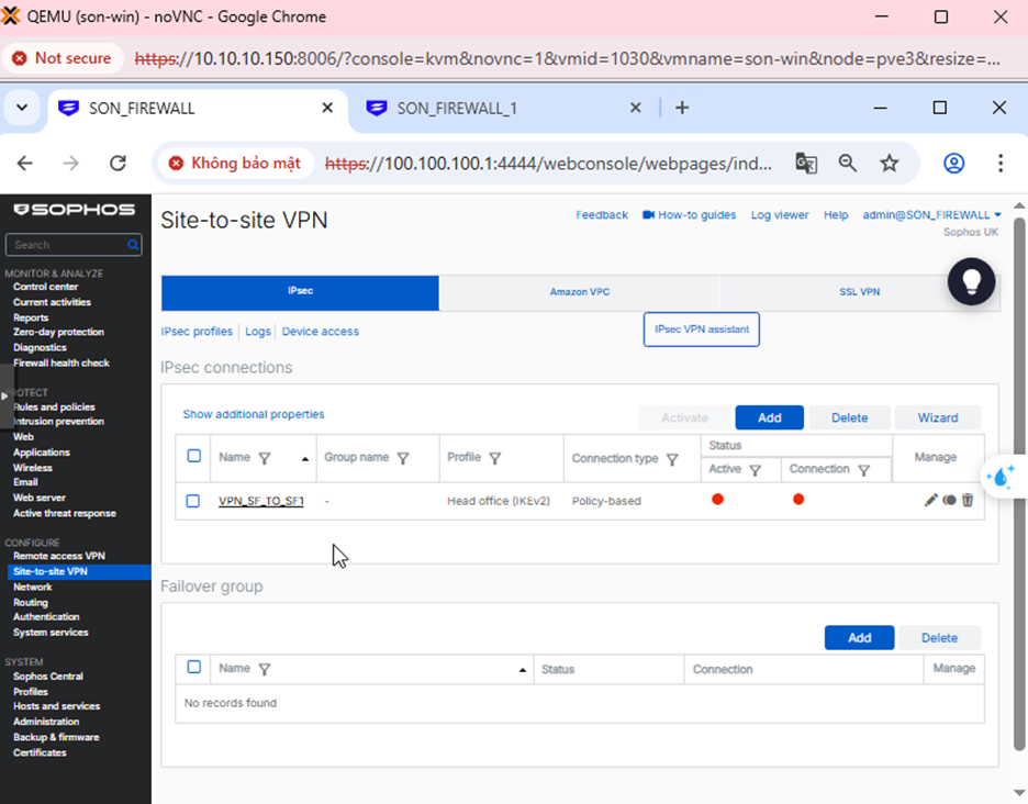
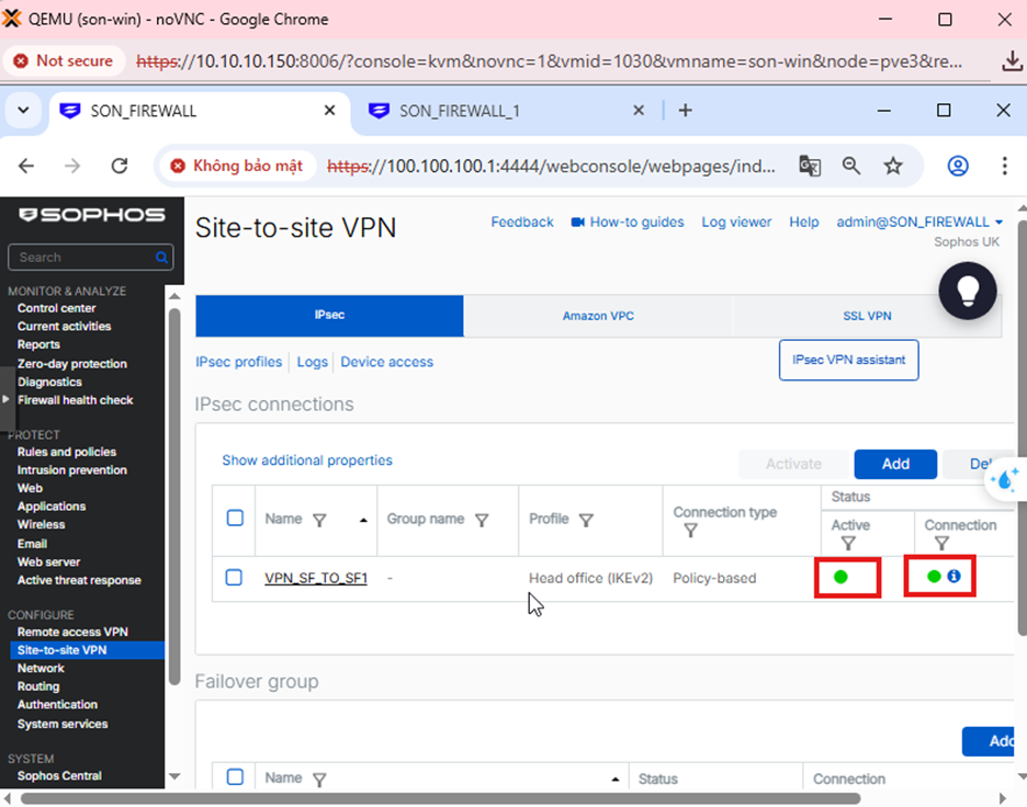
Step 6: Check VPN status
Go to Site to site VPN → IPsec → Check Active and Connection to enable the configuration.
Go to Hosts and services → IP Host → Add to add the local and remote LAN network as shown below.
Step 1: Create an IPsec VPN connection to Firewall 1
Go to Site-to-Site VPN → IPsec and select Add.
Create the connection with the parameters below.
Step 2: Create Firewall Rules for Firewall 2
Go to Rules and Policies → Firewall rules → Add as shown below.
Step 3: Check VPN status
- Go to Site to site → IPsec → Check Active and Connection to start the connection.
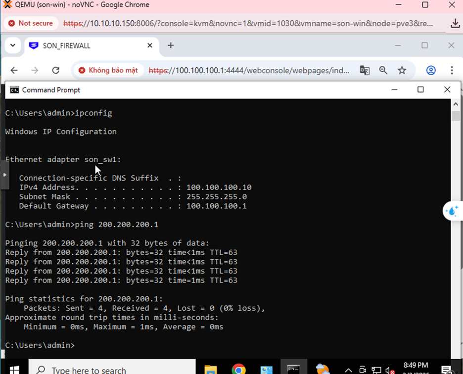
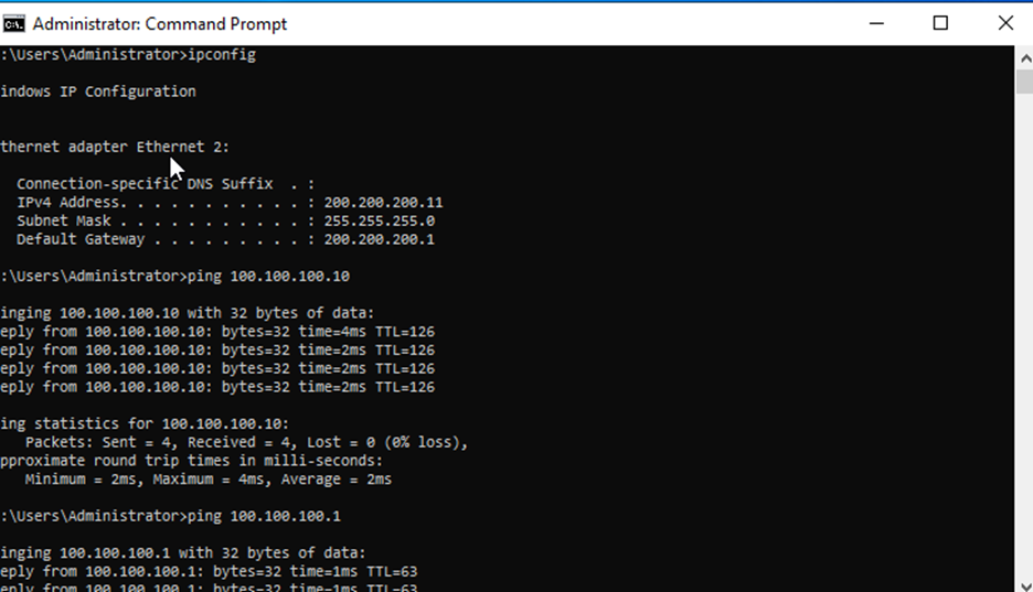
- From a computer in LAN 100.100.100.0/24, ping a computer in LAN 200.200.200.0/24 → ping successful.
- Conversely, from a computer in LAN 200.200.200.0/24, ping a computer in LAN 100.100.100.0/24 → ping successful.